Cooling System – BullSequana XH3000
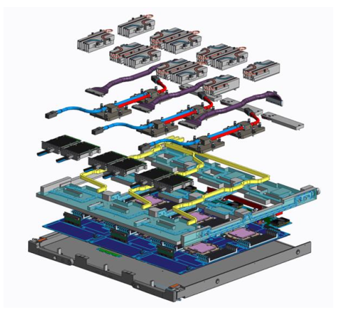
Fig. 1: Perun blade cooling.
Cooling efficiency can reach ca. 97%, with primary water inlet temperatures up to 40 °C. Warm-water operation reduces dependency on mechanical chillers and supports energy-efficiency.
Direct Liquid Cooling Concept
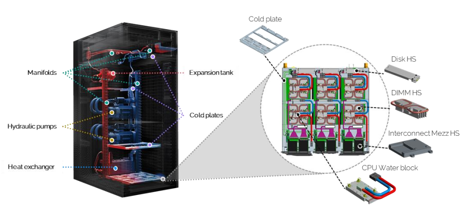
All high-power components inside the rack are cooled by direct contact with liquid-cooled cold plates. Heat is transferred from silicon components to the coolant without relying on high-volume airflow. This eliminates the need for high-speed fan assemblies and reduces acoustic noise and auxiliary power consumption.
The DLC system cools:
- CPUs and GPUs
- Memory modules (via heat spreaders)
- Local storage devices
- High-speed interconnect switches
- Power conversion units
DIMM modules are not directly water-cooled but use dedicated heat spreaders that conduct heat toward the main cold plate. This ensures uniform thermal behavior while maintaining serviceability.
Hydraulic Architecture
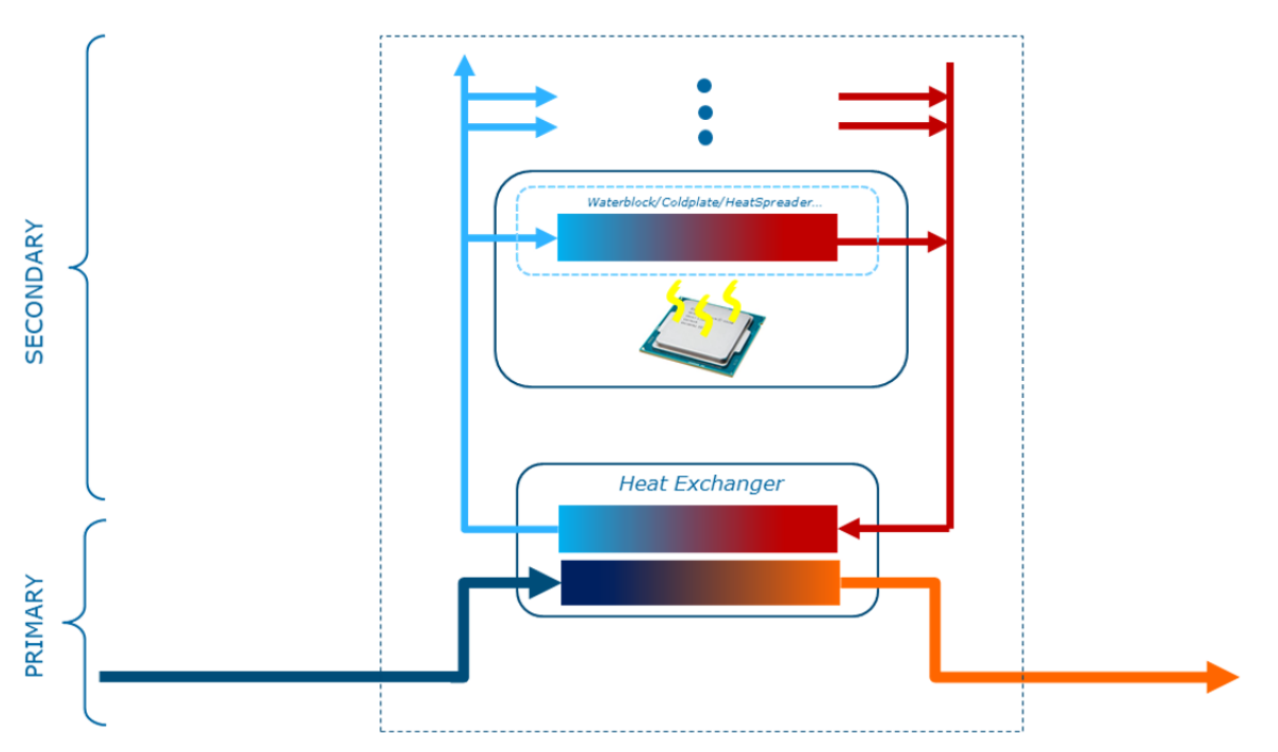
The cooling solution is based on a dual-loop hydraulic architecture composed of a primary (data center) circuit and a secondary (rack-internal) circuit.
The primary circuit is part of the data center cooling infrastructure. It supplies conditioned water to the rack. Primary pumps are located outside the rack and water is cooled by facility-level equipment. The system supports:
- Inlet temperature up to 40 °C
- Outlet temperature up to 50 °C
The primary hydraulic interface uses DN38 insulated hoses (SAE 100R4 standard) with stainless steel fittings and industrial-grade ball valves. Hose configuration can be adapted to specific site requirements.
Inside the rack, the secondary circuit distributes coolant directly to compute blades, GPU modules, switches, and power shelves. Heat from the secondary loop is transferred to the primary loop through a rack-mounted heat exchanger.
This separation ensures that rack-internal components remain protected from potential contamination or quality variations in the facility water supply.
Benefits of the Dual-Circuit Design
The independent primary and secondary circuits provide several operational advantages:
- Protection of compute modules from primary water quality degradation
- Condensation avoidance by regulating secondary loop temperature
- Load-adaptive cooling flow control, reducing operational energy costs
- Stable hydraulic parameters independent of external infrastructure fluctuations
By dynamically regulating primary valve opening based on compute load, the rack optimizes thermal transfer and lowers overall Total Cost of Ownership (TCO).
Redundancy and Reliability
The hydraulic system is designed with redundancy to ensure continuous operation. Two independent cooling chains are implemented within each rack. Each chain includes:
- Hydraulic pump
- Temperature sensor
- Hydraulic Management Controller (HMC)
- Control valve
Under normal operation, one chain is active and the second remains in standby mode. If a fault is detected in the active chain, the system automatically switches to the redundant chain. Simultaneous failure of both chains is considered highly unlikely.